Embedded Systems Part 1 - The Ubiquitous UART
[embedded-systems Practically everyone who has dealt with embedded systems at some point in their life has heard of UART (sometimes simply referred to as serial communication). It’s one of the most popular communication interfaces and remains so despite its age due to its simplicity and ease of use.
What is UART?
UART is short for Universal Asynchronous Receiver/Transmitter. It is a moderate speed communication interface capable of full-duplex communication (meaning it can transmit and receive data at the same time).
A UART interface consists of 2 signals, TX (transmit) and RX (receive).
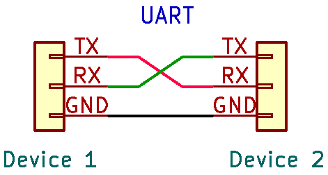
The two devices should have a common ground. This is important because without a common ground reference, neither side can tell what’s a logic high or logic low.
The asynchronous nature of UART means that it doesn’t use a clock signal to pace the transfer of data unlike other communication protocols you may have heard of such as SPI and I2C. But technically, there are clock signals being used, not for synchronizing the transmitter and receiver but internally in the transmitter and receiver that govern how the data is generated and interpreted. These internal clock signals must be sufficiently accurate to the expected frequency of the data transfer and stable.
Looking into the bits
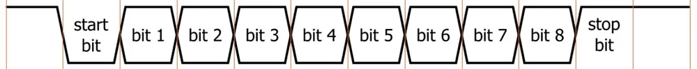
Each UART transmission typically sends 8 data bits or 1 byte. It doesn’t need to be 8 bits (can be anywhere from between 5 to 9) but 8 bits is the most common length as it is exactly 1 byte.
The start and stop of a UART transmission is denoted by a start bit and a stop bit respectively.
The start bit indicates to the receiver that the data line is going to leave its idle state. The idle state is a logic high and the start bit is a logic low, so the start of a transmission can be characterized by a falling edge.
The stop bit has the same logic level as the idle state (i.e. logic high) and indicates the end of the transmission. But this time you can’t characterize the stop bit as a rising edge because the 8th data bit can also be high.
UART transmissions may also employ parity bits. Parity bits are error-detection bits added to at end of the data bits. There are typically three types of parity used in UART which are no parity, odd parity and even parity.
As its name implies, no parity simply just means…. there’s no parity bit. This is actually the most widely used configuration in practice. Since UART is typically used for short-distance communication where transmission errors are rare, the overhead of a parity bit often isn’t worth the minimal error detection it provides.”
Odd parity means that the parity bit will be a ‘1’ if the data byte contains an even number of ‘1’s whereas even parity means that the parity bit will be a ‘1’ if the data byte contains an odd number of’1’s. The idea is to ensure that the number of ‘1’s matches the type of parity (i.e. even number of ‘1’s for even parity and odd number of ‘1’s for odd parity).
Parity bits provide a simple error-detection mechanism, if a bit gets flipped somewhere in the transmission process, the number of ‘1’s no longer matches the parity. Hence the receiver knows that the received data is erroneous. Of course, this strategy doesn’t work at all if two bits are flipped so the parity bit is far from a foolproof solution. However, the use cases of UART are generally simple enough that error detection/correction isn’t really a big concern.
The data rate of the UART transmission is determined by the baud rate, which denotes the number of bits transmitted per second on the wire. Typical baud rates you may encounter are 9600, 19200, 57600, and 115200. In practice, the UART interface can’t transfer data at exactly the baud rate as there is inherent overhead from the start and stop bits (and parity bits if used). For instance, with an 8N1 (8 data bits, no parity, 1 stop bit) configuration, 10 bits are transmitted for every 8 bits of actual data.”
Sampling the bits
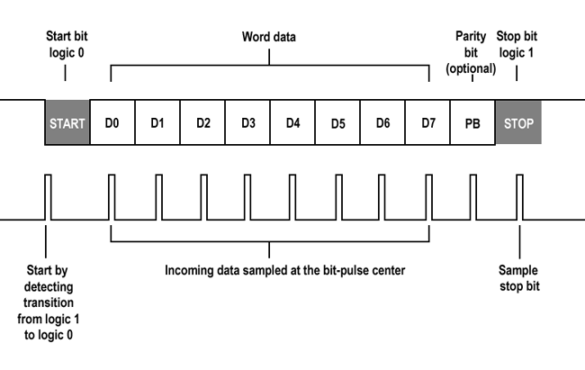
To actually get the data, each incoming bit on the data line must be sampled by the receiver.
In UART, the transmitted bits on the data lines are sampled in the middle of the bit period. This is done because sampling in the middle helps avoid sampling errors due to clock frequency differences between the receiver and transmitter. If you try to sample the start or end of a bit, you might accidentally sample the bit that comes before/after due inaccuracies in the clock.
However there’s a catch: UART is asynchronous, so there’s no clock telling when the transmitter should transmit data and when the receiver should sample the data line. So how does anything even work?
Well there is the start bit, but since the transmitter and receiver clocks are independent of each other, it doesn’t really help as the start bit can arrive at any time at all. In other words, the receiver can miss it or even mistake one of the data bits as the start bit. Even if the start bit was correctly sampled, the receiver wouldn’t know whether it has sampled the start bit at the right time. Too early and you might end up sampling the start bit again on the next clock edge, falsely reading in the start bit as the 1st data bit. Too late and you might skip the 1st data bit, falsely reading in the 2nd data bit as the 1st data bit.
Now you might be thinking, what gives? If UART requires practically perfect accuracy in the transmitter and receiver clock, how does this even work at all?
The solution lies in oversampling. UART receivers are configured to sample the data lines at 8x, 16x or even 32x the baud rate of the UART interface. The more you oversample, the more robust the system is. With 16x oversampling, the system samples the data lines 16 times within each bit period, allowing it to catch each bit with a smaller margin of error. 16x oversampling means the start bit edge detection is accurate to 1/16 (6.25%) of the bit length, meaning it accept a tolerance of 6.25% in the clock’s accuracy.
Now lets look at how a typical UART communication works with a 16x oversampling system, 8 data bits, 1 start bit and 1 stop bit.
- Firstly, the receiver looks for the falling edge of the start bit. This lets the receiver know that a transmission is starting.
- The receiver then looks for the middle of the start bit by waiting for clock edge equal to half the number of clock edges per bit (AKA half the oversampling factor). In this case, since we’re oversampling by 16x, it waits for 8 clock edges. By knowing where the middle of the start bit’s period is, incoming bits can also be sampled at the middle of their own bit period.
- Now at the middle of the start bit’s period, the receiver then counts 16 more clock edges. This brings it to the middle of the first data bit’s period and the first data bit is sampled, storing the data into a buffer.
- The receiver then counts another 16 clock edges before sampling the next data bit. This process repeats until all the data bits have been sampled and stored. After for the predetermined number of data bits, the receiver then looks for the stop bit, characterized by a logic high.
It’s important to note that UART data is shifted out LSB first. This means that if you send a bit sequence like ‘11100101’, the receiver will instead see ‘10100111’.
Footnote
Why serial and not parallel communication?
Serial communication is the form of communication where each bit is shifted out and read sequentially. Nearly all communication in embedded systems is done serially.
So why not do things in parallel? Wouldn’t it be faster to shift out all the bits at once? Yes, it would. However this would mean that you need a separate data line for each bit which is highly impractical. Just sending one byte in parallel would require 8 separate wires. Besides, CPU clocks are incredibly fast nowadays (in the MHz or GHz) range such that any speed advantage from parallel communication is pretty much nil.
UART vs Asynchronous Serial Communication
Pardon my pedantry, but in actuality, what I’ve talked about in this entire post is actually not called UART but is actually Asynchronous Serial Communication. UART technically refers to the hardware chip that is responsible for managing the serial communication on the circuit level. However, in practice UART is typically used to mean the asynchronous serial communication protocol associated with it.
USART
Short for Universal Synchronous Asynchronous Receiver Transmitter, USART is basically just a UART chip that also has the ability to handle synchronous serial communication.